
Networking principles 1: Types of Networks
 A network is a group of two or more nodes connected through a medium. A node is a device, such as a laptop, desktop computer, router, printer, or even your Blackberry–basically any electronic device you use every day at work or at home. The medium might be a wireless connection like radio or infrared waves or a networking cable. A basic network might be two computers connected through a cable, known as a point-to-point (PPP) network. Larger networks are a collection of PCs, laptops, routers, switches, printers, and any device that can connect to the network.
Networking is the principle of designing, implementing, and managing a collection of computers and devices or a network.
Network Topology Explained
Types of Networks
The type of network you have is determined by a number of factors, including:
- Network scale, or the size of your network
- Connection methodology, how your devices connect to your network.
- Network architecture, the design of a computer network
- Network topology, the arrangement of devices in a network.
- Network protocol, a set of rules which is used by computers to communicate with each other across a network
Network Scale
This is how your network occupies space. A local area network (LAN) is a private network that uses high-speed connections to connect one or more subnets, or segments of the network. As the name implies, this is usually confined to a specific geographic area. A wide area network (WAN) is a group of networks in different geographic areas usually connected through an Internet service provider. A global area network covers the entire world and can be thought of as a group of WANs; an example is the Internet.
Connection methodology

This refers to the method by which your devices connect to your network. These methods include Optical fiber, Ethernet, Wireless LAN, HomePNA, Power line communication and G.hn.
Fiber optics consist of long, thin fibers of glass wrapped in protective coating. Instead of more traditional electrical signals, fiber optics use light signals. Because of this, fiber optics are not as susceptible to electrical interference. Transmission speed could go up to as high as trillions of bits per second. The speed of fiber optics is hundreds of times faster than coaxial cables and thousands of times faster than twisted-pair wire.
Ethernet uses physical wiring to connect devices. Frequently deployed devices include hubs, switches, bridges and routers.
ITU-T G.hn technology uses existing home wiring (coaxial cable, phone lines and power lines) to create a high-speed (up to 1 Gigabit/s) local area network. Coaxial cable is frequently used for cable television systems, office buildings, and other worksites for local area networks. The cables consist of copper or aluminum wire wrapped with insulating layer typically of a flexible material with a high dielectric constant, all of which are surrounded by a conductive layer. The layers of insulation help minimize interference and distortion. Transmission speed range from 200 million to more than 500 million bits per second.
Twisted-pair wires are the most common connection type for telecommunications. These can consist of unshielded twisted pairs (UTP), which are more susceptible to interference, or the slightly more expensive but less susceptible shielded twisted pairs (STP). These are most commonly used as telephone wires.
Wireless connections
- Terrestrial Microwave – Terrestrial microwaves use Earth-based transmitter and receiver. The equipment look similar to satellite dishes. Terrestrial microwaves use low-gigahertz range, which limits all communications to line-of-sight. Path between relay stations spaced approx. 30 miles apart. Microwave antennas are usually placed on top of buildings, towers, hills, and mountain peaks.
- Communications Satellites – The satellites use microwave radio as their telecommunications medium which are not deflected by the Earth’s atmosphere. The satellites are stationed in space, typically 22,000 miles above the equator. These Earth-orbiting systems are capable of receiving and relaying voice, data, and TV signals.
- Cellular and PCS Systems – Use several radio communications technologies. The systems are divided to different geographic area. Each area has low-power transmitter or radio relay antenna device to relay calls from one area to the next area.
- Wireless LANs – Wireless local area network use a high-frequency radio technology similar to digital cellular and a low-frequency radio technology. Wireless LANS use spread spectrum technology to enable communication between multiple devices in a limited area. Example of open-standard wireless radio-wave technology is IEEE 802.11b.
- Bluetooth – A short range wireless technology. Operate at approx. 1Mbps with range from 10 to 100 meters. Bluetooth is an open wireless protocol for data exchange over short distances.
- The Wireless Web – The wireless web refers to the use of the World Wide Web through equipments like cellular phones, pagers,PDAs, and other portable communications devices. The wireless web service offers anytime/anywhere connection.
Network topology
Network topology is a description of how your devices, also called nodes, are physically connected to each other. Any particular network topology is determined only by the graphical mapping of the configuration of physical and/or logical connections between nodes. Distances between nodes, physical interconnections, transmission rates, and/or signal types may differ in two networks and yet their topologies may be identical. There are seven basic types of physical topologies.
Bus Topology
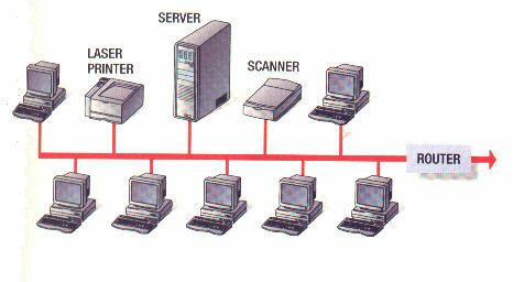
In this topology, each device is connected to a single central cable using a connector. This central cable is then equipped with terminators at each end to prevent signals from bouncing back and forth. A signal from the source travels in both directions to all machines connected on the bus cable until it finds the MAC address or IP address on the network that is the intended recipient. If a computer does not have the correct address, it ignores the signal; otherwise, it accepts the data. Bus topologies are relatively inexpensive to operate; however, if the central cable fails, the entire network will go down.
Linear bus is a type of network topology in which all of the nodes of the network are connected to a common transmission medium which has exactly two endpoints (this is the ‘bus’, which is also commonly referred to as the backbone, or trunk) – all data that is transmitted between nodes in the network is transmitted over this common transmission medium and is able to be received by all nodes in the network virtually simultaneously (disregarding propagation delays).
Distributed bus is a type of network topology in which all of the nodes of the network are connected to a common transmission medium which has more than two endpoints that are created by adding branches to the main section of the transmission medium – the physical distributed bus topology functions in exactly the same fashion as the physical linear bus topology (i.e., all nodes share a common transmission medium). This differs from tree topography in that there is no central node to which any other nodes are connected, since this hierarchical functionality is replaced by the common bus.
Star Topology
In star topology, each device is connected to a central hub. All traffic passes through this hub, which acts as a signal booster or repeater and allows the signal to travel greater distances. This topology is the easiest to set up, and it is also simple to add new machines as your networking needs grow. If the central hub fails, the entire network will go down.
An extended star topology has one or more repeaters between the central hub and the host machines. These repeaters allow the transmissions along the network to cover greater distances.
A distributed star topology is a series of basic star topologies daisy-chained together in a linear fashion with no central connecting point.
Ring Topology
In ring topology, each computer is connected to the network in a loop or ring. In this topology, the signal passes from computer to computer in the form of the token. Only the computer that is currently in possession of the token can send data, and only if there is not already data on the token. The machines or computers connected to the ring act as signal boosters or repeaters which strengthen the signals that transverse the network. The primary disadvantage of ring topology is the failure of one machine will cause the entire network to fail.
Mesh Topology
In mesh topology, some or all of the devices are connected to more than one other device. A fully connected mesh topology is one in which every device is connected to every other device. This makes it possible for one device to send data to all other devices simultaneously. This is usually considered too complex and costly for large networks.
In partially connected mesh networks, only some of the nodes are connected to more than one devices. This makes it possible to take advantage of some of the redundancy that is provided by a physical fully connected mesh topology without the expense and complexity required for a connection between every node in the network.
Tree Topology

Tree topology, also known as a hierarchical network, is one in which a root node is connected to one or more other nodes that are one level lower in the hierarchy (i.e., the second level) using point-to-point links. Each second-level node can then be connected to a third-level node, and so on. This creates the branches of the tree. A tree topology must have at least three hierarchical levels and at least two branches; otherwise, it becomes a star topology or a linear topology network.
If the nodes in a network that is based upon the physical hierarchical topology are required to perform any processing upon the data that is transmitted between nodes in the network, the nodes that are at higher levels in the hierarchy will be required to perform more processing operations on behalf of other nodes than the nodes that are lower in the hierarchy. Such a type of network topology is very useful and highly recommended.
Logical Topology
The logical topology describes how data transmissions travel over the network. This can vary from the physical topology; for example, IBM’s Token Ring is physically a star network but acts logically like a ring network. Logical topologies have classifications similar to physical topologies and are generally determined by the Datalink Layer, Layer 2, of the seven-layer network protocol. The Datalink Layer is concerned primarily with moving data from one device to the next, in contrast to Layer 3, the Network layer, which is only concerned with end-to-end connections. Media Access Control (MAC) addressing is at layer 2. The layer 2 at each device re-encapsulates the message with the new MAC address of the next hop. Layer 2 is also concerned with media the message is transmitted over, like wireless or Ethernet. It handles media access control, the process by which devices can access and transmit over the network.
Network architecture
In general terms, network architecture refers to a design framework for communications networks. This lays out physical components, data format, functional organization and configuration, and its operational principles and procedures. This applies to telephone systems, the Internet, and your office’s computer network.
Get Certified!
Networking Supplies
[simple-rss feed=”http://rest.ebay.com/epn/v1/find/item.rss?keyword=%28computer+workstations%2Cnetworking%29&categoryId1=58058&sortOrder=BestMatch&programid=1&campaignid=5337337555&toolid=10039&customid=USB&listingType1=All&lgeo=1&feedType=rss” limit=10]