
Trunking and VLANs
Routers are typically used to break up large networks into manageable subnets, also called broadcast domains, which is useful if you do not want frequent broadcasts to overwhelm your network. Switches can do effectively the same thing if you set up Virtual LANs (VLANs). The properties of VLANs give them the following advantages:
- Makes your network more efficient. By breaking up your network into a series of VLANs, it won’t be slowed down by broadcasts racing from one end of the network to the other. Devices have to process fewer broadcasts that may contain messages that weren’t meant for them.
- Can improve security. You will likely set up VLANs along roughly the same lines that you would set up group permissions in your servers’ Active Directory if you work for a fair-sized organization. Each department or security level has its own VLAN.
- Better flexibility for expansions. Your VLAN doesn’t particularly care where in a building a particular device is if it has a dynamic configuration. If it is configured to recognize that device, it will think the device is on the same segment.
VLANs are essentially designed to work each on their own subnet. By default, a host in one VLAN can’t reach a host in another VLAN. A Layer 3 device, like a router, is required for communication between VLANs.
Dynamic and Static VLAN
Ports can be assigned to VLANs dynamically or statically. In a dynamic VLAN, devices can join a VLAN based upon its MAC address. This allows users the flexibility to connect to any switch without having to call their network administrator for a new configuration. Dynamic VLAN configuration relies on a VLAN Management Policy Server (VMPS).
Static VLAN configurations are less flexible and rely on devices remaining in place. The network administrator sets up a static VLAN, connects the devices to their ports, and must change the configuration if devices are moved.
VLAN Links
Switches use frame tagging to forward traffic meant for separate VLANs. Switches add a header containing a VLAN ID to each frame going out. They can also read the VLAN IDs for incoming packets to know which VLAN they are destined for. Frames with VLAN IDs travel over links known as trunk links. Switch ports are characterized as trunk links or access links.
An access link, or access port, can be a member of only one VLAN. Devices connected to the switch ports configured to be access links do not see any other VLAN. The switch does the work of adding the VLAN ID to frames destined for the trunk link and removing it when traffic destined for hosts on its access link arrives. Access links are mostly used to connect switches to hosts.
Trunk Links
Trunk links are the switch ports connected to a network switch, router, or server and are characterized by their need to deliver traffic from other VLANs. When a switch receives traffic from the trunk link, it uses the VLAN ID to identify the VLAN it came from in a method called frame tagging. Once the VLAN ID serves its purpose, it is removed. Trunk links have five possible modes:
- ON: Makes the port a permanent trunk even if other configured devices are not configured to use that line as a trunk link.
- OFF: The switch does not use that port as a trunk line even if connected devices are set to use it as a trunk.
- AUTO: The port can become a trunk line but this is optional. It will become a trunk line if the connected device is configured as on or desirable. If both devices on the line are set to auto, the line will not become a trunk.
- Desirable: The port actively seeks to become a trunk line and will succeed if the connected device is set to on, auto, or desirable.
- No-Negotiate: The port is prevented from negotiating a trunk connection. It will be forced into either Access or Trunk mode according to the set configuration.
Encapsulation Methods
Cisco switches will typically use either the Cisco-proprietary ISL or the open IEEE 802.1Q standard to encapsulate frames with the VLAN ID header. ISL is becoming less common in newer Cisco devices, which will often default to 802.1Q. It is best not to assume this, because you may be working with a network that still uses relatively older devices.
802.1Q can support up to 4096 VLANs, as compared to only 1000 supported by ISL. 802.1Q will also tag all frames from all VLANs with the exception of the native VLAN, which is left untagged. You can configure which VLAN is native on any particular trunk.
You can actually tell a Layer 3 switch to function as a Layer 2 device on a particular interface by using the switchport command.
Switch(config)# interface fastethernet 0/1
Switch(config-if)# switchport
Switch(config-if)# switchport mode trunk
Switch(config-if)# switchport trunk encapsulation dot1q

For some switches, such as the Cisco Catalyst 2950 model pictured at left, switchport may not work because they already function at the Layer 2 level. The 2950 also won’t recognize the switchport trunk encapsulation dot1q command due to the fact that it only has one encapsulation method available. When you use the switchport command, be sure the interface is configured as the trunk link.
Configuring VLANs
The command show vlan will display the VLANs that already exist on a switch. VLANs can be created using the vlan <vlan#> command, as in the table below:
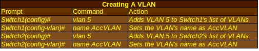
You’ll notice that I use the exact same commands for both Switch1 and Switch2. Using the same VLAN number and name for both makes it easier for both network administrators who might have to troubleshoot their VLANs and routers that send data over the line. Next, both switches will need to know which ports they will use for the VLAN:
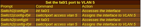
Now if you use the show vlan command, you should see 5 RnD active Fa0/1 as part of the output. This tells you that VLAN 5 has a name of RnD, is active, and is working on the Fa0/1 port.
To configure the interface fa0/5 the trunk, use the commands below:
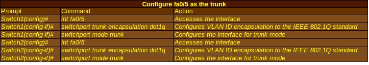
If you type in show interface trunk, it should now show that the trunk interface fa0/5 is on and running the 802.1Q standard. As a reminder, the switchport trunk encapsulation dot1q command will not work on some routers, such as the Cisco 2950 Switch model, which can only run 802.1Q.
If you want to erase your entire VLAN configuration and start over, use the delete vlan.dat command. The IOS will prompt you to confirm the delete.
Inter-VLAN Routing
Switches can handle traffic within a VLAN very well, but because many of them are classed as Layer 2 devices, you will need Layer 3 devices such as routers to communicate between VLANs. The trunk link is typically a link between the switch and a router. The interface on a router can be divided into logical subinterfaces that are seen by the router as separate interfaces and can be used to support distinct VLANs. This concept is called router on a stick and can make a single router with limited physical ports better able to deal with multiple VLANs. A typical subinterface might be labeled fa0/1.5 with the decimal point matching the VLAN it is a member of and a configuration to match.
Troubleshooting VLANs
VLANs should be fairly straightforward even though beginning Cisco administrators will have to practice to get the hang of them. When there are problems with a VLAN, it is usually a configuration error.
- Inter-VLAN Routing Not Working: This is usually a problem with the router configuration and/or the links between switches and routers. Use the command show interface trunk to see the required data. The relevant VLANs should be allowed and the router’s subinterfaces should be configured for the correct encapsulation standard (remember, there are at least two that routers and switches could recognize). The subinterface’s IP address should be the default gateway for hosts trying to send packets through the router.
- VLANs cannot be created: The VTP mode on the switch should not be set to client when configuring VLANs. Make sure you aren’t exceeding the maximum number of VLANs allowed on the switch. The show vtp status command will display the important information.
- Hosts within a subnet can’t reach each other: This may be an IP addressing problem. Hosts within the subnet should have IP addresses within the allowed subnet’s IP address range and the IP address of each device should be unique. If the devices are not on the same switch, check that the VLAN is set up and configured correctly.
Download the MIMIC Virtual Web for CCNA

More Networking Supplies from eBay
[simple-rss feed=”http://rest.ebay.com/epn/v1/find/item.rss?keyword=Cisco+switch&categoryId1=58058&sortOrder=BestMatch&programid=1&campaignid=5337337555&toolid=10039&minPrice=50&listingType1=All&lgeo=1&topRatedSeller=true&feedType=rss” limit=5]