
Wireless Networking Basics II: Physical Layer Standards
In 1978, the International Organization for Standardization (ISO) released the Open Systems Interconnection (OSI) reference model, which describes how computers with different specifications can be connected to a network. This was meant to portray the series of steps computers use to communicate over a network. The model was revised in 1983 and is still widely used today.
The OSI Model
A more in depth discussion of the OSI model
Narrowband Transmission
The radio frequency spectrum is divided into 450 sections known as bands. Radio signals naturally transmit on only one frequency or on a very narrow portion of those frequencies. This is known as narrowband transmission. Radio stations take advantage of narrowband transmissions by transmitting on only one frequency, such as 89.5 or 101.5 FM. Because these transmissions need to exceed the noise level, or total amount of outside noise that might interfere with the original signal, by a substantial margin, narrowband transmissions usually require more power for their signal to be transmitted.
Narrowband transmissions are vulnerable to interference from another radio signal being transmitted at or near the same frequency. If you have two stations transmitting powerful signals on two similar frequencies in the same area, they will interfere with each other. To help cut down on this problem, the Federal Communications Commission regulates the frequencies that radio stations in any given area can transmit on.
Spread Spectrum Transmission
Spread spectrum transmission is an alternative to narrow band transmission that takes a narrow weaker signal and spreads it over a broader portion of the radio frequency band. This allows for lower power consumption because this reduces the effect of noise on the transmission. Most radio receivers will ignore spread spectrum transmissions as noise, allowing for greater security and creating less interference with other systems.
Frequency Hopping Spread Spectrum (FHSS)
Frequency Hopping Spread Spectrum was a concept pioneered by two World War II-era Hollywood neighbors, Hedy Lamart and George Antheil. While they were discussing the problem of Nazis jamming the signal used for guiding U.S. torpedoes, music composer Antheil commented that it might be possible to coordinate rapid changes to a transmission’s radio frequencies in the same way he had once coordinated 16 synchronized piano players. Together, Lamart and Antheil worked on the idea and applied for a patent for their “Secret Communication System” in 1941. The invention called for slotted paper rolls similar to player-piano rolls to synchronize frequency changes in a radio transmitter and receiver. Originally, 84 frequencies were used. The concept was not implemented during the war, but, in the 1950s, the military applied the concept to secure military communications.
With FHSS, the radio frequency used for a transmission will change rapidly during the course of the transmission. The first short burst is transmitted at one frequency, the second at another frequency, and so on. The amount of time spent on a specific frequency is known as the dwell time, and the sequence of changing frequencies is known as the hopping code.
According to FCC regulations, all FHSS systems in the 900 MHz band must hop through 50 channels and cannot spend more than four tenths of a second on one frequency for every 20 seconds of transmission time. FHSS systems in the 2.4 GHz band must hop between 15 channels and the maximum power output cannot be more than 124 mW.
FHSS is not widely used in WLAN systems; however, Bluetooth does make use of it in the 2.4 GHz frequency. Bluetooth changes frequency 1600 times a second.
Direct Sequence Spread Spectrum (DSSS)
Direct Sequence Spread Spectrum (DSSS) is a modulation technique. Like all other spread-spectrum techniques, the transmitted signal takes up more bandwidth than the information signal that is being modulated. This technique makes use of a continuous string of pseudorandom PN code symbols known as “chips.” These chips have a shorter duration than an information bit because the information transmitted using this method is modulated by a sequence of chips. DSSS also uses a signal structure in which the sequence of chips produced by the transmitter is known a priori by the receiver. The receiver can then use the same PN sequence to counteract the effect of the PN sequence on the received signal in order to reconstruct the information signal.
DSSS makes use of a pseudorandom transmission sequence of 1 and -1 values and multiplies the data being transmitted by a “noise” signal. This creates a transmission frequency much higher than that of the original signal, thereby spreading the energy of the original signal into a much wider band. This creates an effect similar to “white noise” or static; the only real difference between this and actual static is that a receiver can extract meaningful data from the transmission by multiplying it by the same pseudorandom sequence. This process is known as “de-spreading.”
For de-spreading to work correctly, the transmit and receive sequences must be synchronized. This requires the receiver to synchronize its sequence with the transmitter’s sequence via some sort of timing search process. However, this apparent drawback can be a significant benefit: if the sequences of multiple transmitters are synchronized with each other, the relative synchronizations the receiver must make between them can be used to determine relative timing, which, in turn, can be used to calculate the receiver’s position if the transmitters’ positions are known. This is the basis for many satellite navigation systems.
The resulting effect of enhancing signal to noise ratio on the channel is called process gain. This effect can be made larger by employing a longer PN sequence and more chips per bit, but physical devices used to generate the PN sequence impose practical limits on attainable processing gain.
If an undesired transmitter transmits on the same channel but with a different PN sequence (or no sequence at all), the de-spreading process results in no processing gain for that signal. This effect is the basis for the code division multiple access (CDMA) property of DSSS, which allows multiple transmitters to share the same channel within the limits of the cross-correlation properties of their PN sequences.
As this description suggests, a plot of the transmitted waveform has a roughly bell-shaped envelope centered on the carrier frequency, just like a normal AM transmission, except that the added noise causes the distribution to be much wider than that of an AM transmission.
In contrast, frequency-hopping spread spectrum pseudo-randomly re-tunes the carrier, instead of adding pseudo-random noise to the data, which results in a uniform frequency distribution whose width is determined by the output range of the pseudo-random number generator.
Benefits of DSSS include resistance to intended or unintended jamming, sharing of a single channel among multiple users, and a reduced chance that a transmission will be intercepted.
OSI and IEEE standards
IEEE wireless standards follow a slightly modified version of the OSI model, which was primarily meant for wired communications. For example, IEEE split the Data Link model into the Logical Link Control and Media Access Control sublayers. The Logical Link Control (LLC) sublayer provides a common interface, reliability, and flow control, while the Media Access Control (MAC) sublayer appends physical addresses to the frame. These sublayers allow higher-level protocols to interact with Data Link layer protocols without regard to Physical layer specifications.
The IEEE also subdivided the Physical (PHY) layer into the Physical Medium Dependent (PMD) and Physical Layer Convergence Procedure (PLCP) sublayers. The PMD sublayer makes up the standards for the characteristics of the wireless medium, such as DSSS, and defines the method for transmitting and receiving data through that medium. The PLCP sublayer reformats the data received from the MAC layer (while transmitting) into a fraim that the PMD can transmit. PLCP also “listens” to the medium to determine when data can be transmitted.
The IEEE WLAN standards specify that the functions of the Physical and the Media Access Control layers should be transparent to the upper layers of the IEEE model, so that no other modifications to the other layers are needed. To accomplish this, some of the networking features usually associated with the higher layers of the OSI model are performed at the MAC layer for wireless LANs.
Legacy WLANS
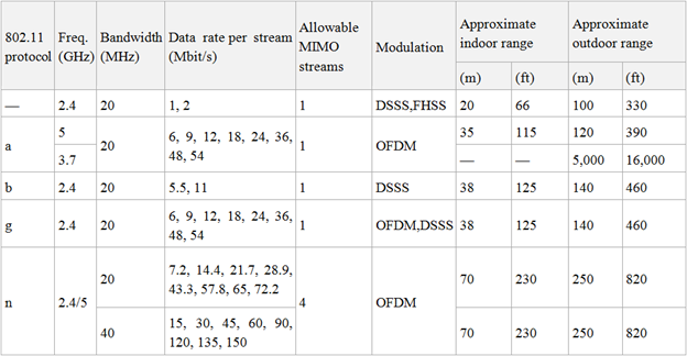
Considering how brief the history of wireless networking is, it might sound odd to refer to some wireless devices as “legacy.” However, wireless technology has advanced so rapidly that most of the earliest WLANs would now be considered obsolete. Two such obsolete standards include the original IEEE 802.11 standard (with no letter) and HomeRF.
The IEEE 802.11 standard of 1997 allowed for cable-free data access for clients in a mobile or fixed location with a speed of up to 2 Mbps. These devices could use either FHSS or DSSS for RF transmissions, but FHSS and DSSS devices could not “talk” to each other. 802.11 also allowed for diffused infrared transmissions.
HomeRF was based on a protocol called the Shared Wireless Access Protocol (SWAP), which had been established by the HomeRF Working Group. This group was made up of over 50 companies which manufactured and sold home electronics. This protocol defines a set of specifications for wireless data and voice communications around the home. Devices could be as far apart as 45 meters (150 feet) and had a speed of up to 10 Mbps. Devices could include computers, cordless phones, and home entertainment equipment. HomeRF was never as popular as IEEE WLANs and the HomeRF Working Group disbanded in 2003.
IEEE 802.11b Physical Layer Standards
The basic purpose of the 802.11 PHY layer is to send and receive signals to and from the network. It is divided into the PMD and PLCP sublayers.
The 802.11b Physical Layer Convergence Procedure (PLCP) standards are based on DSSS transmissions. While preparing data for transmission, PLCP reformats data received from the MAC layer into a frame that the PMD sublayer can transmit. This frame consists of three parts. The preamble prepares the receiver for the rest of the frame. The header consists of information about the frame itself. Lastly, the data, or payload, portion of the frame consists of the actual data being transmitted. The payload can be anywhere from 1 to 16,384 bits in size.
The Preamble is further divided into two parts: the Synchronization field and the Start Frame Delimiter field. The Synchronization field allows the receiving device to prepare for an incoming message. The Start Frame Delimiter field is always the same bit pattern (1111001110100000) and defines the beginning of the frame.
The Header consists of 4 parts. The Signal Data Rate defines the designated speed of the signal. The Service field is typically set to 00000000 and is reserved for future use. The Length consists of the value of the length of the frame. The Header Error Check field contains data that can be used to check for errors upon receipt of the frame.
The Data part of the transmission only consists of the Data field which contains the information to be transmitted. The Preamble and Header are always transmitted at 1 Mbps. This allows slower devices to talk to faster ones.
Physical Medium Dependent Standards
Once the frame is created, the PLCP passes it on to the Physical Medium Dependent (PMD) sublayer. The PMD’s job is to translate the 1’s and 0’s of binary language into radio signals for transmission. The 802.11b standard uses the Industrial, Scientific, and Medical (ISM) band for its transmissions and specifies 14 frequencies that can be used, beginning at 2.412 GHz and incrementing by .005 GHz, except for Channel 14, which is 2.484 GHz.
With 802.11b, two different types of modulation can be used. For transmissions at 1 Mbps, a two level phase shift key (PSK) known as differential binary phase shift keying (DBPSK) is specified. The phase change for PSK bit 0 is 0 degrees and the phase change for bit 1 is 180 degrees. For transmissions at 2, 5.5, and 11 Mbps, a four level phase change called differential quadrature phase shift keying (DQPSK) is used. This phase change allows four variations in phases for the bits 00, 01, 10, and 11.
802.11b also defines the type of DSSS coding to be used. DSSS uses expanded redundant code, also known as Barker code, to transmit each data bit. This code is used when transmitting at 1 or 2 Mbps. For rates above 2 Mbps, complementary code keying (CCK) is used instead. This coding consists of 64 8-bit code words that have unique mathematical properties which allows a receiver to correctly read them.
IEEE 802.11a Physical Layer Standards
802.11a is a bit of an oddball, in that IEEE released this standard after 802.11b. Revisions to the Physical layer of 802.11a allow it to transmit at speeds up to 54 Mbps. This increase of speed was primarily due to its use of OFDM multiplexing. 802.11a also introduced improved error checking, a higher frequency, and access to more transmission channels.
This standard makes use of the Unlicensed National Information Infrastructure (U-NII) band. This band is intended for devices that provide short-range, high-speed wireless digital communications.
U-NII Characteristics
- U-NII 1 (Low Band) makes use of the 5.15-5.25 GHz band. It has a maximum power output of 50 mW.
- U-NII 2 (Middle Band) makes use of the 5.25-5.35 GHz band. It has a maximum power output of 250 mW.
- There is an unnamed band that makes use of the 5.46-5.725 GHz band. It has a maximum power output of 1000 MHz.
- U-NII 3 (High Band) makes use of the 5.725-5.825 GHz band. It has a maximum power output of 1000 MHz. This band is most commonly used for building-to-building wireless transmissions.
Disadvantages of U-NII
One disadvantage of U-NII is that, in some countries, the 5 GHz bands are allocated for uses other than WLANs. In Japan, U-NII 3 is reserved for outdoor applications. In Europe, U-NII 1 has a maximum power output of 200 mW instead of 50 in the U.S. This is generally not a problem for WLANs confined to a single country, but international companies and travelers may find it necessary to maintain different networks in different countries.
Another disadvantage relates to the growing amount of outside interference. A growing number of electronic devices, including cordless phones, are beginning to operate within the 5 GHz range. Such interference is a major source of problems for WLANs.
802.11a Channel Allocation
Increased channel allocation is another reason for the faster speed of 802.11a. Up to eight frequency channels can overlap and operate simultaneously in U-NII 1 and U-NII 2. Within each frequency channel, there is a channel 20 MHz wide that supports 52 carrier signals, with each signal 300 KHz wide. The center points for the 8 channels are 5.18, 5.20, 5.22, 5.24, 5.26, 5.28, 5.30, and 5.32 GHz. Each AP will only use one channel at a time, regardless of how many are available.
Error Correction
With 802.11a, the number of errors are greatly reduced because transmissions are sent over parallel subchannels. This minimizes radio interference from outside sources. Forward Error Correction (FEC) makes use of 4 of the 52 subchannels to transmit secondary copies of data sent over a wireless network. Sophisticated algorithms can use these secondary transmissions to recover lost data in the primary transmissions. This helps eliminate the need to retransmit data if the first transmissions are lost.
PLCP Revisited
- The preamble is strictly meant for synchronization of the transmitter and receiver in the 802.11a standard. This field consists of 10 repetitions of a short training sequence and 2 repetitions of a long training sequence. This part of the transmission lasts 16 microseconds.
- The Header consists of six fields. The rate field specifies the transmission rate of the data field and is 4 bits in length. The Reserved field is reserved for future use. The Length field indicates the length of the Data field, which is between 1 and 4095. Parity is used for error checking. The Tail indicates the end of the Header; all six of this field’s bits are set to 0. The Service field is used to synchronize with the receiver; all of its bits are set to 0 and the last nine bits are reserved for future use. Although Service is part of the header, it is transmitted at the same rate as the data field.
- The actual data to be transmitted is contained in the Data field. The length is between 1 and 4095 bits. The IEEE standard specifies that the number of bits in the Data field must be a multiple of 48, 96, 192, or 288, so the Data fields are often “padded” with extra bits.
IEEE 802.11g Physical Layer Standards
The success of the two previous standards prompted IEEE to revisit them both to see if they could create a hybrid of the two that would bring out the best traits of both. They also received input from a number of chip manufacturers, who had a stake in the outcome. The result was IEEE 802.11g, which was released in June 2003.
802.11g makes use of the 2.4 GHz ISM frequency. It makes use of two mandatory modes: Complementary code keying (CCK) at 11 and 5.5. Mbps and OFDM for 54 Mbps. It also has one optional mode, Packet Binary Convolution Coding (PBCC-22) for 22 Mbps.
802.11g maintains backwards compatibility with 802.11b devices, making it easy for 802.11b users to upgrade simply by replacing the APs.
IEEE 802.11n
802.11n makes use of multiple antennas to create the ability to send and receive signals at the same time. This is called Multiple Input, Multiple Output (MIMO). MIMO can handle up to four MIMO streams at the same time. It can handle speeds up to 300 Mbps. If you bought a “pre-n” device before the standard was officially released in 2009, you may have realized that it was a marketing gimmick by now and upgraded the firmware to match changes from initial drafts and make sure it stays functional.
…Didn’t they release a new standard recently?
You were obviously paying attention if you knew about a new standard called 802.11ac. It features more channel bonding, denser modulation and double the MIMO channels of 802.11n.
Wireless Networking Supplies For Your Consideration
[simple-rss feed=”http://rest.ebay.com/epn/v1/find/item.rss?keyword=Wireless+Networking+Supplies&categoryId1=58058&sortOrder=BestMatch&programid=1&campaignid=5337337555&toolid=10039&customid=USB&listingType1=All&lgeo=1&feedType=rss” limit=5]